
FreeCAD Extension (Year 7 Robotics)
An extension to dt7/Workshop 1 Hardware and Networks's sibling, Workshop 2: Robotics & Smart Devices.
So you've finished your Sphero hat in TinkerCAD and you want to know what the "grown-up" 3D tools look like. This page is for you. It's optional. Your Workshop 2 booklet does not need any of this.
What FreeCAD adds on top of TinkerCAD
TinkerCAD is brilliant for getting a shape out of your head and onto the print bed fast. You drag blocks, you combine them, you export. Done.
FreeCAD is a different kind of tool. It's parametric, which means every part of your design remembers how it was made. If you decide the hole in your Sphero hat needs to be 74 mm across instead of 72 mm, you change one number and the whole model updates — holes, pockets, fillets and all. That's how real engineers design things they might have to tweak later. It is slower to learn, but it gives you precise control and a workflow that looks a lot like what people use in industry.
FreeCAD is free, open source, and runs on Windows, Mac, Linux and Raspberry Pi. There is no account to make and nothing to pay for.
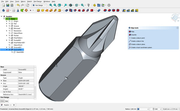
FreeCAD 1.0 in the Part Design workbench. The tree on the left shows every step used to build the model. Image by Maxwxyz, CC BY 4.0, via Wikimedia Commons.

Where to start
These are the resources I'd point a Year 7 student at first. They are all free, and none of them try to teach you everything in five minutes.
- FreeCAD Getting Started (official docs) — The official wiki's beginner page. Calm, written, step-by-step, and it matches whatever version you install.
- Download FreeCAD — Grab version 1.0 or newer. The installers are straightforward; ask an adult if you're on a school laptop.
- MangoJelly Solutions — FreeCAD for Beginners (YouTube) — Joko's channel is the one most people recommend first. Slow voice, clear screen, no flashy edits. Start with his "FreeCAD 1.0 Beginners" playlist.
- FreeCAD Part Design Tutorial (official) — A written walkthrough of the Part Design workbench. This is the workbench you'll use for almost anything you'd print.
- FreeCAD Forum — Help — When you get stuck, search here first. The community is patient with beginners as long as you describe what you tried.
If you only pick one, start with the official Getting Started page and keep MangoJelly open in another tab for when the written version doesn't click.
Worked example: a small Sphero hat in FreeCAD
Here's a quick look at the steps. Don't try to follow exact clicks from this page — use it as a map, then follow the docs linked at each step.
Step 1 — Open Part Design
File > New, then switch the workbench dropdown to Part Design. This is where you'll do almost all your 3D modelling. (Part Design docs)
Step 2 — Sketch a circle
Create a new sketch on the XY plane. Draw a circle, then add a diameter constraint and type the number — say, 80 mm for a hat that sits over a 72 mm Sphero. Constraints are what make FreeCAD parametric: the circle isn't just "about that big", it's exactly 80 mm, and FreeCAD remembers that rule. (Sketcher docs)
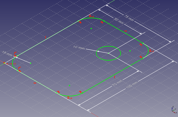
A sketch with constraints. The white dimension arrows lock the shape to exact measurements. CC0, via Wikimedia Commons.

Step 3 — Pad it into a disc
Close the sketch, then use Pad to push it upwards by 10 mm. You now have a solid puck — a flat cylinder. (Pad docs)
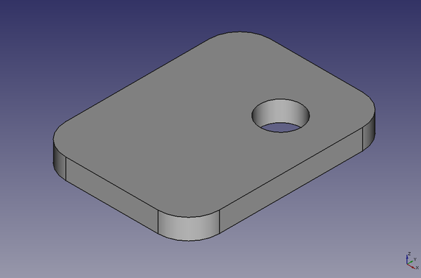
After padding the sketch, you get a solid 3D shape. CC0, via Wikimedia Commons.

Step 4 — Pocket out the underside
Make a new sketch on the bottom face, draw a 72 mm circle, and use Pocket to cut it 8 mm deep. That hollow is where the Sphero sits. (Pocket docs)
Step 5 — Fillet the edges
Use Fillet on the top edge to round it off. Try a 3 mm radius first — you can always change it later. (Fillet docs)
Step 6 — Export for printing
Select the body in the tree, File > Export, and choose STL. That file goes straight into your slicer (like Cura or PrusaSlicer). (Export docs)
The parametric payoff
If your hat turns out too tight, open the sketch from Step 2, change 72 to 73, and everything updates automatically. You don't have to rebuild a thing. That's the whole point of parametric design.
Cross-link
This page extends the "Designing a Hat for Your Robot" task in Workshop 2. For the core task you only need TinkerCAD — see the Workshop 2 page (coming soon) once it's up on the wiki.
This is an extension page — not required for the Workshop 2 core task. TinkerCAD is fine for everything in the booklet. Last updated: April 2026.
← Back to dt7/Year 7 Hub